Blog

View our latest blogs below – included are top tips, guides, product updates, new releases and webinars.

    How to change units in Autodesk Inventor 2023

    About Units of Measure

    For parts, assemblies, and presentations the template file sets the default units used in a file. For drawings, the active standard and the dimension style specified in the template file sets the units.

    The template is typically a file named Standard. xxx in the template folder. The default template units are specified when you install Inventor.

    Override Units in Parts, Assemblies, and Presentations

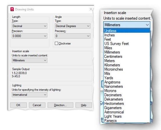
    To change the default unit of measure in the active file, go to Tools tab  Options panel  Document Settings and then select the Units tab in the dialog box. Select the Length drop-list to change units such as inches to mm. When you change the units setting, all existing values in the file display as the new units. All subsequent entries are displayed in the new units. Unit value settings are saved with the file.

    You can also override the default units in any value box. For example, you can type 12mm in the dimension value box of a file using an inch unit of length. The result is displayed as 0.472, but the original 12mm unit value is retained and appears in the value box when you edit.

    Override Units in Drawings

    In drawings, the dimension style, and the active drafting standard set the units system. Edit the dimension style or drafting standard to change the units system.

    To override the default unit of measure in the active file, do any of the following:

    • Go to Tools tab  Options panel  Document Settings and then select the Standard tab in the dialog box. Select the Active Standard drop-list to change units such as ANSI to ANSI-mm.
    • Go to Manage tab Styles and Standards panel Styles Editor and set the Standard in the Style and Standard Editor dialog box.

    All subsequent entries are displayed in the new units. Unit value settings are saved with the file.

    Change the default units in a template file

    To change the default template file units, do any of the following:

    • Select Configure Default Templates  in My Home or select Tools tab  Options panel  Application Options and then select Configure Default Template in the File tab.
    • Edit the source template file, modify the units, and then save the file.
      • For parts, assemblies, and presentations, set the units in the Documents Settings Units tab.
      • For drawings, either set the units in Document Settings Standards tab or the Style and Standard Editor in the Manage tab.
    Contact Us
    Acceptance

    Credit – Autodesk 

    For more information please contact us today!

    Your Partner for Design Success

    Give us a call on +44(0)1254301888, or email us on hello@quadrasolutions.co.uk and let's talk!

    Get In Touch

    When two leading PCB companies collide

    A solid relationship to champion British manufacturing

    Our success is powered by our commitment to continually explore new opportunities. We can only make this possible with three elements: people, knowledge, and innovation.

    We value and respect these three key elements and never underestimate their potential when brought together. It’s because of our faith in the power of people, knowledge, and innovation that we made a great decision during the coronavirus pandemic – to unite with a UK-based PCB manufacturer, Hi5 Electronics. True artisans of the industry renowned for their reliability and outstanding quality.

    New beginnings based on firm foundations

    In 2021, Quadra Solution’s two owners, Steve Dobson and Simon Dobson were approached by Craig Southern, the owner of Hi5 Electronics with a fantastic proposition. The company had to adapt to keep Hi5’s mission alive and not move away from its vision. It was clear that the three experienced leaders together had a winning combination, one that could address the challenges and uncertainties that Hi5 was facing and take it to a higher level.

    It was agreed that Quadra Solutions and Hi5 Electronics would join forces, empowering them both to be the ultimate ambassadors of British manufacturing with a shared determination to deliver the best PCB services to their clients.

    What this means to you, our customers…

    We never make any decision without stepping into our customers’ shoes first. We asked ourselves, ‘will this decision be better for our customers?’ And the answer was a resounding yes!

    Quadra will remain your design technology partner, continuing to offer our award-winning PCB design bureau, and continue to be specialists in CAD software solutions for mechanical, construction and PCB design industries. None of this will change.

    The strong collaboration will result in a one-stop-shop for everything from the designing of the PCB concept to the finished product with the added bonus of only ever having one point of contact for the entire process.

    That’s not all. The joining of companies allows us to share our expertise and knowledge, reduce risks and development costs, increase efficiencies, access new markets, drive growth, and get you to market faster.

    We can achieve outcomes that might not have been possible previously.

    We’re delighted that you’re a part of this new chapter too

    As you already have an established relationship with us, there really is no need to take your prototyping work elsewhere. Now we can manage this for you guaranteeing the highest levels of expertise and quality that you have come to expect from us.

    Contact Us
    Acceptance
    For more information please contact us today!

    Your Partner for Design Success

    Give us a call on +44(0)1254301888, or email us on hello@quadrasolutions.co.uk and let's talk!

    Get In Touch

    How to get started with eCADSTAR (and what we learnt)

    In this article, we will discuss why you should switch to eCADSTAR and how we can help.

    Knowing how to make the most of eCADSTAR’s useful features and resources can help you avoid those early user mistakes. If you’re new to eCADSTAR, here’s how we suggest getting started:

    Request an online demonstration so you can see eCADSTAR in action and its capabilities.

    Start with the basics. The first thing you should do is familiarize yourself with the program’s GUI & basic selections, such as its file menu, tabs, and icons. You can then go on eCADSTAR’s interactive tour, and work through the inbuilt DIY training.

    Browse through the list of tutorials available on the site. These tutorials will teach you how to use more advanced features, so they’re a handy resource if you’re looking for a quick way to learn something new in your spare time. FAQ’s are available from the start page.

    At Quadra Solutions, we are committed to helping eCADSTAR users with our online resources.

    eCADSTAR is a great tool for beginners and advanced users alike. Our aim is to remove the steep learning curve by providing a streamlined experience including set-up and installation, Migration ,Library management, Schematic capture through to PCB design.

    Our website has a wealth of videos and guides to help you get started with eCADSTAR and how to migrate your designs from CADSTAR.

    We also have a team of technical experts on hand who can help answer your questions about how to use the software effectively and to answer any queries you may have, even if you are not a subscriber yet. You can call, request a teams session or email our support desk. This service helps to get eCADSTAR implemented and up and running within the design office quickly.

    The eCADSTAR software provides an intuitive user interface, which makes it easier for new users to pick up on their first day using it, whether your preference is using ribbons, shortcut keys or right click assist menu’s, eCADSTAR provides extensive options for customisation to suit your personal work flow.

    And if you’re still new to schematic and PCB design software, our eCADSTAR essentials training course will cover everything you need to know to get started.

    Our team will walk you through the basics of eCADSTAR in a 4 day training course that introduces the software and its key features.

    The course takes you through the PCB design process from Library management and Schematic Capture to PCB design and Manufacturing outputs.

    Speak with an experienced eCADSTAR representative who will help answer your questions about how best to use our tools, along with any other questions that come up as a result of using them. Whether you’re looking for more information on licensing or our support options, we will answer any questions or concerns you might have.

    We have produced a series of eCADSTAR getting started guides to help you out.

    The Getting Started Guides are available here and cover the following topics:

    eCADSTAR Online Training Courses

    CADSTAR to eCADSTAR Migration

    eCADSTAR Tutorial Videos

    eCADSTAR has been designed as an easy-to-use but sophisticated tool for designers at all levels of knowledge and experience. eCADSTAR’s intuitive interface makes it easy for beginners to use the software, but advanced users will also appreciate its versatility. With sophisticated tools for High Speed, Creepage, Signal Integrity, Power Integrity, Spice Simulation, IBIS AMI and more.

    Even your mechanical team will appreciate what eCADSTAR has to offer, eCADSTAR’s 3D environment includes mechanical checking, which means mechanical constraints can be checked at PCB design level.

    We hope this blog post has given you a good idea of what to expect when starting out with eCADSTAR. We would love to hear from you if you have any questions about our tools or software, so please feel free to contact us at any time.

    Contact Us
    Acceptance
    For more information please contact us today!

    Your Partner for Design Success

    Give us a call on +44(0)1254301888, or email us on hello@quadrasolutions.co.uk and let's talk!

    Get In Touch

    Quadra Assurance Form

    Quadra Assurance Form
    1) Power User 1 - Essential
    1) Power User 1 - Essential
    First
    Last
    Software Used
    2) Named User 2
    2) Named User 2
    First
    Last
    Software Used
    3) Named User 3
    3) Named User 3
    First
    Last
    Software Used
    4) Named User 4
    4) Named User 4
    First
    Last
    Software Used
    5) Named User 5
    5) Named User 5
    First
    Last
    Software Used
    Start Over
    For more information please contact us today!

    Your Partner for Design Success

    Give us a call on +44(0)1254301888, or email us on hello@quadrasolutions.co.uk and let's talk!

    Get In Touch

    Inventor Read Only Mode

    Back in the day, to view Inventor files without the use of Inventor itself we had to use Inventor View. Now, this was, for the longest time perfectly acceptable. In fact, Autodesk themselves used it as part of the Vault offerings to view their ‘own’ data. Click here to view.

    While Inventor View served its purpose, it did/does have some limitations.

    When accessing files via Inventor view, we are actually seeing the Part / Assembly / Drawing as it was when it was last saved. Now with 3D data, this shouldn’t ever be an issue, but with 2D data there are considerations.

    Do we want to view the drawing as it was last saved (3 weeks ago for example)? or should we be seeing it as it currently is. (taking into consideration the 3D data that has been updated more recently than the last 3 weeks).

    With inventor view, we only see the data as it was last saved (this to be fair is probably a good thing in the case of a released drawing) we cannot view truly up-to-date data.

    Read Only Mode

    With the current crop of inventor, we now have access to Inventor Read Only Mode. Now, this does exactly as it says on the tin, it IS Inventor, but it IS Read Only!

    Using actual Inventor, but with all the ‘creation’ tools removed, we now know that we are looking at the current data, as its stands today, not 3 weeks ago when not was last saved. This means, an Assembly for example now has up-to-date constraints, Drawings show a clean/current view taking into consideration any recent 3D changes.

    With Inventor View, we can only view (including Zoom, Pan, and Orbit) and print models/drawings. When opening the same data with Inventor Read Only Mode, we have access to all the tools in full Inventor but without any editing capabilities. We can interact and query the model browser, use the inspect tools (measure, interference analysis etc), access the BOM in an Assembly and so on.

    Inventor Read Only Mode is installed automatically as a ‘partner product’ to the full Inventor install, which means if you already use Inventor 2020 or newer, you already have access to the software.

    Anyone can get Inventor Read Only Mode. So your colleagues, shop floor personnel, Customers etc can view your Inventor data in full fidelity as it was meant to be viewed.

    To gain access to Inventor Read Only Mode, just download and install the Inventor trial (full Inventor) HERE.

    An Inventor Read Only Mode shortcut  is created which remains available even after the trial expires (30 days)

    Best of all, Inventor Read Only Mode is FREE!

    Tools available with Inventor Read Only Mode

    Parts

    Parts 1

    Parts 2

    Parts 3

    Assemblies

    Assemblies 1

    Assemblies 2

    Assemblies 3

    Assemblies 4

    Drawings

    Drawings 1

    Drawings 2

    In the image below, the top row shows full Inventor Professional, giving us up-to-date information

    On the second row, Inventor ‘Read Only’ (left) & Inventor View (Right) can be seen with the saved information displaying correctly

    Inventor View

    At this point, I have updated and saved the IPT, and then activated the IDW. Full Inventor has automatically updated the IDW with the latest 3D changes and a save is pending.

    On the lower half, we can see the reloaded Inventor ‘Read Only’ has updated the IDW. It has been done to reflect the true current state of the IPT, BUT Inventor View is still showing us the ‘as saved’ data which is now stale.

    Inventor View 2

    Finally, now that I have saved the IDW (top right) within full Inventor Pro, both Inventor ‘Read Only’ AND Inventor View have access to the latest designInventor View 3

    Contact Us
    Acceptance
    For more information please contact us today!

    Your Partner for Design Success

    Give us a call on +44(0)1254301888, or email us on hello@quadrasolutions.co.uk and let's talk!

    Get In Touch

    The difference between Model Space & Paper Space (and how to use it)

    The difference between Model Space & Paper Space (and how to use it).

    So, many users of AutoCAD either don’t know about Paper Space or don’t know how to use it.

    There are many reasons for this, people who have used AutoCAD for many years and they learned it 20 years ago and it did what they wanted so they haven’t continued with learning new techniques.

    Others have seen it but don’t understand the benefits or feel that they just don’t need it.

    All of the above are reasonable arguments but this doesn’t mean they are right.

    Let’s set out the premise of the different spaces

    Model Space; (MP)

    Model space is the environment you draw what you want to make, i.e. The Model.

    Model Space

    This is to be drawn at 1:1 (all detail views can be displayed in Paper Space – More about this later), the format of the “1:1” can be unitless but it is a better practice to use the correct unit, mm, meters, kilometres, inches, feet etc.  This setting is in the Drawing Units Dialogue

    This will allow you to have full control and give continuity of how the non-continuous line types such as hidden, centre & phantom are displayed.

    Paper Space; (PS)

    As the name suggests this environment is all about documentation. Essentially you place a piece of paper in PS and then cut holes in it to view the Model at various scales (or NTS).

    There are several ways to achieve this that we don’t have time for in a blog. But what follows may help to explain a little.

    Working in Paper Space

    In the following video, we will create a Drawing that will always print at 1:1, the drawing has 2 views. 1 will contain all the elevations and will display at 1:2 the other is a detail of the slot hole that will be displayed at 2:1.

    After adding some MText with a field extract the View Ports scale, we will make a simple change to the bearing footprint, you will see the changes in both the 1:2 and the 2:1, we will then change the scale of the viewports and after a regen, the fields will update to reflect the change.

    If you are creating drawings of a similar type (elevations view and details) in MS you will probably appreciate the impact of small detail changes on multiple views. One change in a design could impact many views, you can see from the video that many views can be updated by changing the model in one place. Of course, there will also be a lot of copying and scaling of various sections of the model to achieve detailed views to allow accurate manufacture, assembly or building.

    My opinion on the advantages

    If you are to produce an accurate and streamlined drawing process the use of Paper Space for laying out drawings is a key part of that strategy. The ease at which one can creatin and modify drawings far exceeds anything that can be achieved using Model Space alone in a very short time scale. The use of Paper Space along with annotative annotations and some other tools will change your workflow for the better and more importantly it will make you faster and sage time!

    Contact Us

    Contact Us

    Acceptance
    For more information please contact us today!

    Your Partner for Design Success

    Give us a call on +44(0)1254301888, or email us on hello@quadrasolutions.co.uk and let's talk!

    Get In Touch

    Collaboration in Revit

    Collaborating with your team on a single project file

    Revit has great built-in tools for teams to work on larger projects with the need for multiple copies of files being distributed and then federated on a regular basis, the general term is “Worksharing”

    There are several ways to coordinate and collaborate including creating a central model, using linked models & working within a CDE such as the Autodesk Construction cloud.

    In this blog, we are going to focus on the use of a central model.

    The Central Model – Overview

    A Central Model is a “master copy” of the project file, in this file we have Worksets (see below), each member of the team opens the central mode and this is copied to their local computer.

    A user can take exclusive ownership of a workset or “borrowed” geometry from the central model or another workset. If the geometry is owned by another team member, then a request is placed, when access is granted, the change can be made. If the element is not owned by another team member, permission is automatically granted.

    When the team member synchronizes their design changes to the central model the borrowed assents are released back to the central model and all changes by other team members are synchronized with the local copy.

    Figure 1

    Preparation – Working example

    Create your worksets

    Worksets are a collection of geometry in a logical group.

    The first thing to do is to create worksets based on functional areas.

    This may be as simple as External Wall & Grids, Level 1, Level 2 etc. or if the building is larger, External Wall & Grids, Level 1 (North Wing), Level 2 (North Wing) etc. If you are working on a BIM mandated project, these areas and levels may have already been determined in the contract documents.

    Create a central model

    Once you have created the worksets, Save the file to a location that the whole team has access to (this will probably be a network share) and close the file. (see Figure 3).

    Members of the team can now navigate to the file from the Open command in Revit, at this point Revit will recognise that the file is a central model create a local file in the location referenced in the Options dialogue under “Default Path for user files” (see Figure 3).

    Figure 2

    Figure 3

    As you can see the new local copy refers to the Central model in the Revit Home screen.

    Now each team member can work on the areas of the building that are relevant to their specific needs. As mentioned above the elements can be borrowed or owned during the working day.

    Synchronize with Center

    Do this regularly and relinquish all borrowed items, there is also an option to add a Comment to track the changes that have been made during the work session.

    When opening the file from the Revit Home page you will be offered the option to open the Central Model, this should only be done if changes to the central model are to be made such as adding worksets. N.B. As you can see there is a check box to disable this dialogue if you wish.

    This will overwrite the local copy but not before warning the user.

    You are now ready to start your day’s work, knowing that you have the latest data and all other members of the team are starting with a synchronised data set.

    Good practice

    • Save your local fila regularly.
    • Synchronize with central and relinquish all borrowed items on a regular basis.
    • Relinquish all worksets and borrowed items at the end of the working day.
    • Download a fresh local model at the start of every working day.
    • Compact and repair the central model as part of your ongoing maintenance or if the synchronizing becomes slow. This will clean up the Revit database and remove data that is no longer needed.

    These steps ensure that all team members have the latest information for the team as a whole.


    Contact Us
    Acceptance
    For more information please contact us today!

    Your Partner for Design Success

    Give us a call on +44(0)1254301888, or email us on hello@quadrasolutions.co.uk and let's talk!

    Get In Touch

    How FeTu went from 6 hours to 6 minutes – Inventor Professional

    What is Inventor Professional?

    Inventor Pro is a trusted, professional-grade design and engineering software.  It is a complete design solution, from design to manufacturing and beyond. Inventor can automate complex design workflows as well as everyday repetitive tasks, and it connects your processes from concept through to make, and it promotes collaboration amongst teams and your customers.

    Who are FeTu?

    FeTu was established in 2016 and is based in West Yorkshire. They have created a revolutionary ‘green’ energy device, known as “Roticulate”, targeting carbon reduction across a broad range of industries and applications. This disruptive enabling technology provides a versatile ‘continuous positive displacement’ machine that inherently lends itself to being cost-effective and highly efficient.

    The FeTu ‘roticulating’ concept is perceived as the world’s first ‘quad-acting’ device (duplex double-acting). It is lightweight and scalable and uses just two moving parts to operate four anti-phased compression chambers, offering low-loss conversion from potential to kinetic energy.

    Fetu

    The Challenge

    This concept, developed entirely within Inventor Professional, requires precision engineering and repeat clash-detection analysis throughout every aspect of development. Various design changes can (and invariably do) occur through each project review and FeTu need to ensure that performance is not compromised with each and every assembly update.

    The Problem

    Lots of manual calculations and processes. They’ve got to perform the same tests on all four chambers, taking several hours each. Resulting in up to 2 days’ work per complete analysis. Furthermore, if subsequent changes are required, the engineers have to perform all of the analyses from scratch.

    As the majority of the parameters being applied were repetitive and the data being inputted was being extracted from the model, FeTu was convinced there had to be another way and contacted Quadra to ask if there was anything that could be done to perhaps halve the time it takes to achieve these results.

    …Halve? We can do much better than that….

    The Solution

    Matt Hutchinson, one of Quadra’s Senior Application Engineers, set to work for 7 hours (6.75 to be precise) using Inventor Pro’s built-in iLogic automation environment, to create a modular routine that can now be dropped onto any of FeTu’s Roticulate assemblies. This routine essentially rotates an angle constraint, performs an interference check to report the number of clash instances and volume of each interference, records the results, then increments the angle by 1 degree and repeats …again …and again …tabulating each result into a report and outputting in a format which can then be exported into Excel for interrogation.

    The Result

    “Matt was incredible (he used that word). He has reduced our work from nearly 6 hours to 6 minutes per chamber and we couldn’t be happier” [John Fenton, FeTu Managing Director]

    In conclusion, Inventor’s out of the box capability is industry recognised. But what often goes UNrecognised is just how much you can do when you step ‘out of that box’ and go a few steps further, applying a bit of technical expertise to automate and program Inventor Pro to do much more with your parts and assemblies, much faster, whilst maintaining accuracy from the model data with minimal user input.

    Expand into Inventor Professional

    We get it…  very few people have the expertise to correctly develop routines or modules within Inventor. That’s where Matt and the team can help.

    If you have a similar problem, that’s both repetitive and time-consuming and you have that nagging suspicion that there IS a better way, just do what FeTu did – get in touch and see how we can help!

    Contact Us
    Acceptance
    For more information please contact us today!

    Your Partner for Design Success

    Give us a call on +44(0)1254301888, or email us on hello@quadrasolutions.co.uk and let's talk!

    Get In Touch

    BIM Collaborate Pro – Overview Webinar

    Join us, along with Autodesk’s Paul Hewitt & Jonathan Brookfield (of Tech Data) to learn all about BIM Collaborate Pro (formally BIM 360).

    BIM empowers teams with the coordination tools they need to avoid misalignment, catch errors earlier, and save money. Data is captured across project lifecycles and displayed in powerful dashboards that shine a light on project issues, transparency, and the completion status of major milestones.

    In the webinar we discuss;

    •    Overview of the Autodesk Construction Cloud offerings
    •    What is BIM Collaborate Pro?
    •    BIM Collaborate vs BIM Collaborate Pro
    •    Seamless data throughout the lifecycle
    •    Autodesk Docs functionality
    •    Communication: Managed Collaboration & Model Collaboration module

    Watch the webinar using the link below.

    Contact Us
    Acceptance
    For more information please contact us today!

    Your Partner for Design Success

    Give us a call on +44(0)1254301888, or email us on hello@quadrasolutions.co.uk and let's talk!

    Get In Touch

    How to change or convert the units of a drawing in AutoCAD

    Issue:

    How to change the units of a drawing in AutoCAD, such as from Imperial (feet/inches) to Metric (mm, cm, m), or vice versa.

    Solution:

    These are the main methods to convert drawing units.

    Alternative 1 (preferred method): Use -DWGUNITS

    1. Enter the -DWGUNITS command. The following prompts will be performed in succession:
      1. Drawing units.
      2. Drawing unit display formats.
      3. Linear display format.
      4. Linear display precision.
      5. Scale objects from other drawings upon insert?
      6. Match INSUNITS to drawing units?
      7. Scale objects in current drawing to reflect change in units?
      8. Include objects in Paper Space?
    2. Choose a drawing unit other than the current one on step 1.
    3. On step 7, and optionally step 8, choose Yes.
    Note: According to the chosen options, some prompts may be skipped by pressing Enter.

    See the following example of command-line text ( in red what you have to enter) In this example the drawing will be converted from inches to millimetres:

    Command: -DWGUNITS
    Loading AEC Base...
    Loading AEC Base Extended...
    Loading AEC Core...
    Drawing units:
      1. Inches
      2. Feet
      3. Millimeters
      4. Centimeters
      5. Decimeters
      6. Meters
    Unit for length <1>: 3
    Drawing unit display formats:
      1. Scientific
      2. Decimal
    Linear display format <2>: 2
    Linear display precision <4>: <Enter to accept the proposed 4 for the linear precision>
    Scale objects from other drawings upon insert? [Yes/No] <Yes>: <Enter to to accept the proposed "Yes">
    Match INSUNITS to drawing units? [Yes/No] <Yes>: <Enter to to accept the proposed "Yes">
     ** WARNING: you have changed the unit for this drawing database.  **
     ** All new objects will be drawn according to the new unit, but   **
     ** existing objects will not change size unless you specifically  **
     ** ask to have automatic scaling occur.                           **
    Scale objects in current drawing to reflect change in units? [Yes/No] <Yes>:
    Include objects in Paper Space? [Yes/No] <Yes>: <Enter to to accept the proposed "Yes">
    Scaling the entire database...
    Scaling AecDbObject(s)...
    Scaling entities in Model Space...
    Scaling entities in Paper Space...
    Scaling entities in Paper Space...

    Notes for AutoCAD Plant 3D: This command can only convert plain AutoCAD components like lines, arcs, … but not all AutoCAD Plant 3D components like AutoCAD Plant 3D elbows. Don’t use DWGUNITS for AutoCAD Plant 3D.

    Alternative 2: Use the INSERT command

    In this example, the components will be converted from inches to feet.

    1. Start a new drawing using the acad.dwt template.
    2. Enter the UNITS command.
    3. Select “Decimal” for Type and “Feet” for Insertion scale. Click OK.
    4. Enter the INSERT command (or CLASSICINSERT in AutoCAD 2020 and newer).
    5. Click the Browse button and select the inch-based drawing.
    6. Deselect all options so the drawing will go in at 0,0, no scaling, and no rotation.
    7. Select the checkbox for “Explode” and click OK.

    Alternative 3: Use the SCALE command

    1. At the command line, enter SCALE.
    2. At the Select objects prompt, enter All.
    3. Enter 0,0 for the base point.
    4. When prompted for scale factor, enter the appropriate scale factor for the units to be converted, based on the following list:

    Scale Factors:

    Inches to Millimeters = 25.4
    Millimeters to Inches = 0.0393701

    Inches to Centimeters = 2.54
    Centimeters to Inches = 0.393701

    Feet to Millimeters = 304.8
    Millimeters to Feet = 0.00328084

    Feet to Centimeters = 30.48
    Centimeters to Feet = 0.0328084

    Notes:

    • For the SCALE command method, adjust the dimension text and arrowhead height in the dimension style as needed.
    • Layout viewports may need to be moved or resized, or the plot scale updated, when an alternate unit page size is selected after conversion. For example, when an imperial paper size is selected in a drawing that has been converted to metric.

    For AutoCAD downloads please Click Here 

    Contact Us
    Acceptance
    For more information please contact us today!

    Your Partner for Design Success

    Give us a call on +44(0)1254301888, or email us on hello@quadrasolutions.co.uk and let's talk!

    Get In Touch

    Key Revit Concepts – Modeling, Elements, Parameters & Families

    Key Revit Concepts include Modelling, Elements, Parameters & Families

    Modeling

    In the Revit model, every drawing sheet, 2D and 3D view, and schedule is a presentation of information from the same virtual building model. As you work on the building model, Revit pulls together information across all other representations of the project. It automatically coordinates changes made anywhere—in model views, drawing sheets, schedules, sections, and plans.

    Elements

    Key Revit Concepts
    Revit Elements – Different stages of merging elements

    Elements are the building blocks of a 3D model. They represent the real-world components that a designer adds to the model.

    Some elements—such as walls, windows, and beams—are 3D and appear in all views. You can think of these elements as components that exist in a building. Other elements—such as tags, dimensions, or other annotations—appear only in the view in which they are placed.

    These elements maintain rules and relationships to each other. For example, when a roof is attached to walls, a relationship between the elements is established. These rules and relationships make changing the model easier.

    Parameters

    Parameters define the size, shape, position, material, and other information about an element in the model. Parametric modeling refers to the relationships among all elements in a project that enable the coordination and change management that Revit provides. These relationships are created either automatically by the software or by you as you work. Here are some examples:

    • A door is a fixed dimension from an adjacent partition wall. If you move the wall, the door retains this relationship to the wall.
    • The edge of a floor or roof is related to the exterior wall so that, when you move the exterior wall, the floor or roof remains connected.
    • Rebar is spaced equally across a given element. If you change the length of an element, Revit maintains equal spacing among elements.

    Families

    All the elements you add to your Revit model are organized into families. This includes walls, doors, structural members and mechanical equipment. Or annotation elements such as elevation symbols, door tags and column gridlines.

    A family is a collection of elements with identical use, common parameters, and similar geometry. For example, although you may have different sizes of desks, all the sizes can belong to a desk family. If you look in the Project Browser, you can see a branch called Families.

    We offer a range of different Revit training courses – to find out more information use the links below or contact us by clicking here.

    • Autodesk Revit Architecture Fundamentals Training
    • Revit Template and Family Creation Training
    • Autodesk Revit MEP Fundamentals
    • Revit Structure Fundamentals
    • Autodesk Revit Collaboration Tools
    • Revit Architecture: Site and Structural Design Training
    • Autodesk Revit Conceptual Design and Visualisation Training
    • Revit for Project Managers
    Contact Us
    Acceptance
    For more information please contact us today!

    Your Partner for Design Success

    Give us a call on +44(0)1254301888, or email us on hello@quadrasolutions.co.uk and let's talk!

    Get In Touch

    Inventor Model States

    Inventor Model States is a powerful new workflow that has been added to the new Inventor release. Model States let you create manufacturing states, simplification levels, and more in the same part or assembly file.

    Inventor Model States

    At the same time, Model States represent the implementation of some of the most highly requested functionality In Inventor. You can now create multiple representations of a part or assembly within a single document.

    This new workflow provides a convenient way to engineer, manage, and manufacture your designs, as variations exist in one file, thus, there is no need to worry about breaking associations between files.

    Use Model States to represent:

    • Manufacturing stages
    • Simplification levels
    • Product families
    • Adjustable or flexible parts

    Each Model State can contain different:

    • Dimensions
    • Features
    • Components/Bill of Materials
    • iProperties
    • Parameters

    By changing the Edit Scope toggle in the browser, you can decide if edits apply only to the active member or all members.

    Edit Scope Toggle

    What can I do with Model States in Parts?

    Model States in Parts

    Use part model states to capture manufacturing processes, create part families, create adjustable and flexible parts, or create simplified versions of a part.

    Each Model State can have unique parameters, properties, and suppression states.

    Sheet metal parts also benefit from model states. By using Model States you can now create configurations with unique folded features and flat patterns.

    Create Configurations

    What can I do with Model States in Assemblies?

    What can I do with a Model State?

    You can use an assembly model state to create and capture:

    • Assembly variations and families of components
    • Manufacturing processes
    • Assembly stages
    • Assembly level features
    • Substitutes
    • Simplified assemblies
    • Unique weldment preparation, weld, and machining features

      Introducing Inventor Model States

    Drawings

    You can select a model state when creating a drawing view. A Parts List displays the selected model state members and their iProperties.

    Inventor Model States

    A view created from a Substitute model state reflects the state of the substitute part in the drawing view.

    Lastly, please note: If you need separate files that can be managed and released, consider using iParts and iAssemblies.

    Contact Us
    Acceptance
    For more information please contact us today!

    Your Partner for Design Success

    Give us a call on +44(0)1254301888, or email us on hello@quadrasolutions.co.uk and let's talk!

    Get In Touch
Product Inquiry - Get started Now
Start Over